HOME > Engineering Info > Allowable Load
Load and Moment
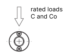
A load as shown in Figure 1-1 is applied to the linear system.
In addition, a moment may be applied, and in NB, the load in each direction is expressed as follows.
Load |
 |
Direction Moment |
 |
Basic Static Load Rating (compliant with ISO14728-2*1) and Allowable Static Moment
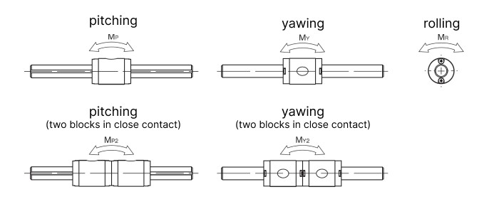
When excess load or impact load is applied to the linear system while it is stationary or moving slowly, a permanent deformation occurs on the rolling elements and the race way. If this deformation exceeds a certain limit, it causes vibration and noise during operation resulting in a non-smooth motion and a shorter life time. To prevent this permanent deformation and deterioration in motion accuracy, the basic static load rating (Co) is given as the allowable load for the linear system. This basic static load rating is defined as the static load that results in the maximum allowable stress at the center of the contact surface between the rolling elements and the race way. The sum of the permanent deformation of the rolling element and that of the race way is 0.0001 time the diameter of the rolling element. In the linear system, a moment load may be present in addition to the static load. The allowable static moments are defined by MP, MY, and MR as illustrated in the figure above.
*1: This does not apply to some products.
Allowable Load and Static Safety Factor
The basic static load rating and allowable static moment define the maximum static load in each direction, however, these maximum static loads are not necessarily applicable depending on the operating conditions, the mounting accuracy, and the required motion accuracy. Therefore, an allowable load with a safety factor must be obtained. The minimum static safety factor is listed in the table below.


